

Accelerator Physics

Magnet
HALF is a fourth-generation, low-energy synchrotron light source operating at a beam energy of 2.2 GeV with an ultralow natural emittance below 85 pm·rad. The facility comprises a full-energy linear accelerator and a soft-X-ray, diffraction-limited storage ring with a circumference of 480 m. In total, 680 main magnets—including longitudinal-gradient dipoles (LGBs), quadrupoles (Q), sextupoles (S), octupoles (O), and reverse bends (RB)—are deployed across the ring’s 20 cells. Fig. 1 shows the layout of a standard cell, in which most multipole families must be adjustable over approximately 80–125% of their nominal strengths (and in some cases beyond), a requirement that can drive elevated pole-tip fields. Despite the associated technical challenges, all magnets have been successfully fabricated.
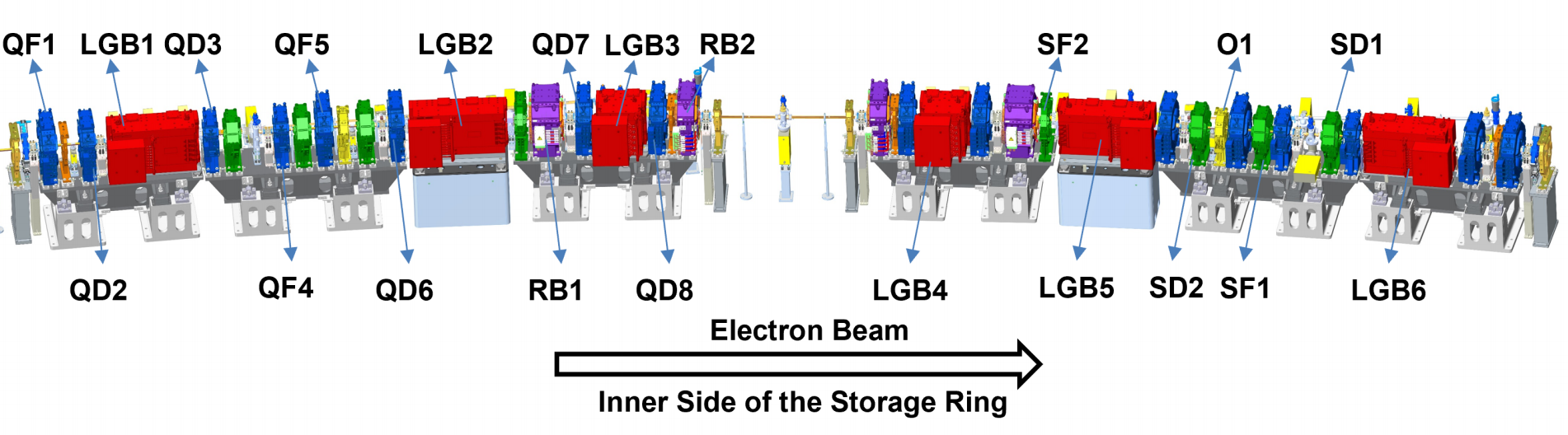
Fig. 1. Schematic view of one cell of the HALF lattice.
To achieve the theoretical minimum emittance (TME) at fixed ring circumference and dipole count, HALF employs LGBs whose field varies along the electron trajectory, thereby reducing emittance beyond the theoretical-minimum-emittance limit. Although permanent-magnet LGBs demonstrated at modern facilities are compact and inexpensive to operate, their limited adjustability is incompatible with HALF’s need for future energy upgrades. HALF therefore adopts an electromagnetic, variable-gap LGB concept that provides large and continuous tuning longitudinal field—to the best of our knowledge, the first formal deployment of such variable-gap electromagnetic LGBs in a fourth-generation synchrotron light source worldwide. Table 1 summarizes the principal parameters of HALF’s LGBs. Fig. 2 shows the three types of LGBs after final machining.
Table 1. Specifications of longitudinal gradient bending magnets of HALF
Magnet | LGB1/6 | LGB2/5 | LGB3/4 |
Maximum field (T) | 0.6287 | 0.7928 | 0.9000 |
Trajectory length (m) | 0.212 for 5 steps | 0.230 for 5 steps | 0.180, 0.200/0.180 |
Gap (mm) | 30.8/33.9/45.5/57.1/69.5 | 55.6/48.0/34.4/31.2/43.3 | 31.1/30.4/31.1 |
Trajectory deviation (mm) | ≤0.1 | ||
GFRa,* (mm) | ± 13 mm | ± 13 mm | ± 8 mm |
*GFR indicates the Good field region along the trajectory where field deviation is within 0.05%.
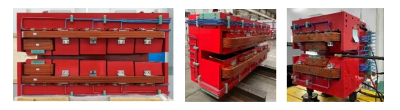
Fig. 2. Physical images of LGB1, LGB2, and LGB3.
Using the NSGA-II–based magnet-design methodology, we completed the physics design of all multipole magnets for the HALF storage ring and carried out pole shape shimming of the LGBs, achieving excellent design outcomes. Fig. 3 presents photographs of each type of the multipole magnet in the storage ring.
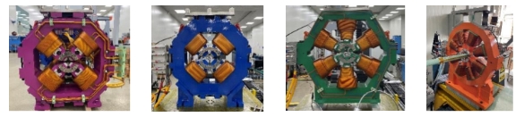
Fig. 3. Physical images of reverse bends, quadrupole magnets, sextupole magnets, and octupole magnets.
Magnet Measurement
The magnet measurement team is responsible for measuring the magnetic field of the linear accelerator and the storage ring. To conduct the magnetic field measurements, we have developed three types of measurement equipment: the rotating-coil system, the stretched-wire system, and the Hall probe system.
The rotating-coil system, as shown in Fig. 4, based on Faraday’s law of induction, is designed to measure the integrated field gradient, multipole field components, and magnetic center. It is specifically used to evaluate the characteristics of quadrupoles and sextupoles. One of the most important technical parameters of the rotating-coil system is its measurement reproducibility. Our system's performance in measuring multipole field components has achieved approximately 20 ppm, which is considered top-class performance domestically.
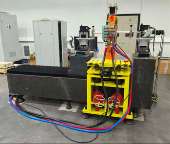
Fig. 4. The rotating-coil system
The stretched-wire system, as shown in Fig. 5, is designed and manufactured to measure the integrated field strength and the magnetic center. It consists of a single wire that passes through the magnet bore, allowing for slight movements in both horizontal and vertical directions. The induced voltage in the wire is proportional to changes in the magnetic flux. We use this system to determine the magnetic center of multipole magnets and for magnet fiducialization. Our approach achieves a magnetic center measurement precision of less than 2 micrometers and an overall uncertainty in magnet fiducialization of less than 10 micrometers. Compared to other methods available worldwide, we have reached an advanced level of accuracy.
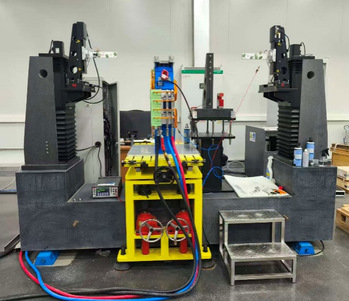
Fig. 5. The stretched-wire system
The Hall probe system, as shown in Fig. 6, which operates based on the Hall effect, measures magnetic flux density in three dimensions with high sensitivity and accuracy. This system is used to assess the field strength of bending magnets and to calibrate the integrated field of multipole magnets. One of the most critical technical parameters of the Hall probe system is its reproducibility in measuring the integrated field, which we have achieved at approximately 20 parts per million—a leading domestic standard.
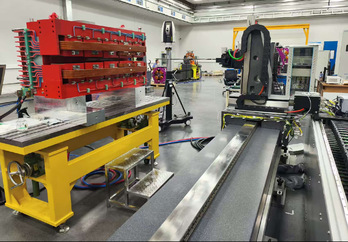
Fig. 6. The Hall probe system
Injection
The function of the injection system is to inject the beam from the transport line into the storage ring. The beam is accumulated and replenished at a specific time intervals, achieving the top-up operation mode. HALF employs a combined injection scheme utilizing an anti-septum magnet for local orbit bump injection and a nonlinear magnet (NLK) for single pulsed multipole magnet injection.
A schematic of the local bump injection scheme is shown in Fig. 7. A dual-channel kicker (anti-septum) is installed downstream of the septum. The 2-Ch kicker, in conjunction with conventional Kickers K1 and K3, is designed to induce a local bumped orbit with unequal strengths. Meanwhile, the injected beam passes through the 2-Ch kicker without additional deflection. In this injection scheme, the separation between the injected and stored beams can be minimized, thus reducing the demand on the DA. The NLK is located between K2 and K3. The two off-axis injection schemes are compatible and all the required magnets can be installed in one long straight section.
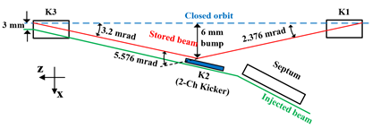
Fig. 7. Schematic of the modified local bump injection scheme for HALF.
RF
The beam lifetime is one of the most important parameters that synchronous radiation users are concerned about, and it directly determines the performance of the electron storage ring. The RF system consists of a main 500 MHz superconducting (SC) cavity and a passive 1.5 GHz SC 3rd-harmonic cavity for the HALF storage ring.
The function of the superconducting (SC) main rf system is to provide cavity voltage for the beam in the storage ring in order to replenish the energy loss caused by radiation. Meanwhile, it provides a good high-order mode(hom) environment to reduce the coupling bunch instability for the beam current. The system mainly includes one set of 500 MHz sc rf module, one set of solid state power source, one set of power transmission system, and one set of digital low-level system (DLLRF) and safety interlock system, etc. The 3D layout diagram of the system is shown in Fig. 8. Some local optimizations have been made to the cavity type and size for the 500 MHz sc rf cavity of the HALF in order to deeply suppress the high-order modes while maintaining a relatively high Q value.
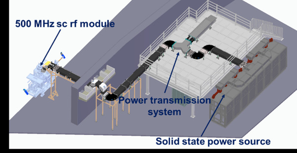
Fig. 8. The 3D layout diagram of the HALF sc main rf system.
The function of superconducting (SC) 3rd-harmonic cavity is to lengthen bunch and to improve beam lifetime in HALF storage ring. The entire module of SC 3rd-harmonic cavity is listed in Fig. 9. The longitudinal length is calculated to be 1844 mm and the height is 2450 mm. This SC 3rd-harmonic cavity is unique in terms of cavity geometry with two different-radius beam pipes. The fabrication process is much simpler than those of SC harmonic cavities with fluted beam pipes. It should be noted here that the helium vessel is welded to the SC 3rd-harmonic cavity in order to avoid cavity vacuum leak inside the thermal cycles, as shown in Fig. 10. This is quite different from other SC modules in which between the helium vessel and the SC cavity are separated.
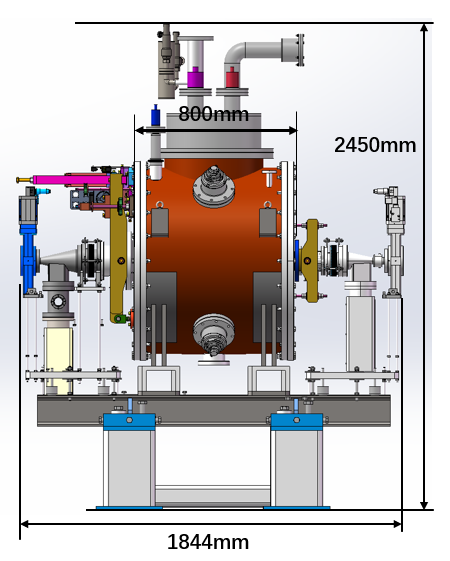
Fig. 9. The entire module of SC 3rd-harmonic cavity for HALF.
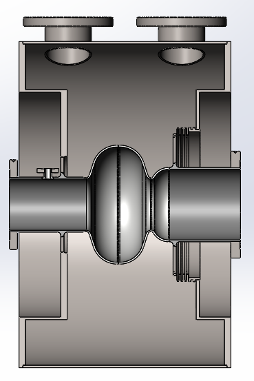
Fig. 10. The helium vessel is welded with the SC 3rd-harmonic cavity.
Vacuum
The storage ring vacuum system creates an excellent ultra-high vacuum environment for the electron beam, ensuring its long-term, high-quality, and stable operation within the storage ring. It serves as one of the key infrastructures and fundamental guarantees supporting HALF in achieving its designed scientific goals. With a circumference of 480 meters, the HALF storage ring vacuum system is divided into 20 vacuum units. It comprises a series of components including zirconium-copper vacuum chambers, stainless steel vacuum chambers, shielding bellows, photon absorbers, vacuum valves, vacuum gauges, and pumps.
So far, a series of challenges have been overcome. We have addressed the manufacturing challenge of fabricating vacuum chambers with extremely small apertures and complex, specially-shaped cross-sections from high-performance materials. This involves precision welding, forming, and machining techniques, where even minor deformations or defects could disrupt the electron beam path, leading to degraded beam quality or loss. We have also overcome the technical hurdles in applying Non-Evaporable Getter (NEG) coatings to small-aperture vacuum chambers to achieve and maintain extremely high vacuum levels within narrow spaces under strong synchrotron radiation irradiation. Fig. 11 and Fig. 12 show the coating technics of circular-cross-section vacuum chamber and vacuum chamber with antechamber.
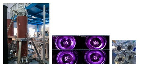
Fig. 11. Coating technics of circular-cross-section vacuum chamber.
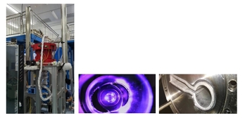
Fig. 12. Coating technique of vacuum chambers with antechamber.
HALF vacuum system is the first in the world to use ZrCu alloy as the structural material for accelerator vacuum chambers, as shown in Fig. 9. Additionally, an elongated NEG (Non-Evaporable Getter) cartridge specifically tailored for HALF vacuum pipelines has been developed, featuring high pumping speed, large gas sorption capacity, and low activation temperature.
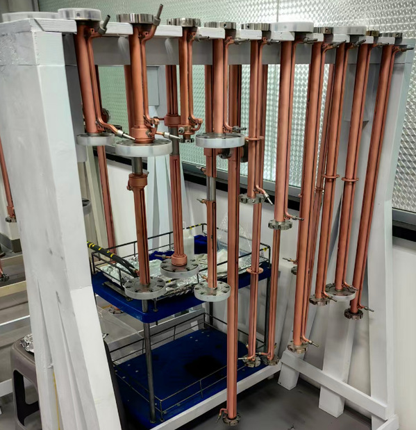
Fig. 13. ZrCu vacuum chamber.
Beam Diagnostics
The Beam diagnostics system for HALF storage ring plays a critical role during commissioning, acceptance test, and user operation stages. It provides precise and comprehensive beam parameter information to evaluate machine performance, while offering real-time data and diagnostic tools for accelerator physicists. The system enables measurements of beam position, intensity, lifetime, filling pattern, betatron tune, beam profile/emittance, bunch length, and real-time beam loss. Additionally, it implements bunch-by-bunch feedback and fast orbit feedback to ensure orbit and beam stability.
The specifications and corresponding solutions of beam diagnostics system for HALF storage ring are summarized in Table 2.
Table 2. Beam Diagnostics Specification and Solution for HALF Storage Ring
| Sub system | solution | specification | quantity | |
Transverse position | Button pickup + home made DBPM | SA (10Hz): 50 nm FA (20kHz): 100 nm TBT: 500 nm | 240+5 | |
Beam current | DC | Bergoz NPCT + DMM | 2 uA @ 1 Hz | 1 + 1 |
Filling pattern | stripline pickup + PLL 1GHz digitizer | 0.05% @ 1 kHz | 1 | |
Tune monitor | Turn by turn FFT / MBFB | 0.001 | 1 | |
Beam size | Xray focusing | Xray SR + Zone plate + Xray CCD | better than 2 um | 1 |
Xay pinhole | Xray SR + pinhole + Xray CCD | better than 5 um | 1 | |
Bunch length | SR + streak camera | better than 2 ps | 1 | |
MBFB | Transverse | Stripline kicker + iGp12 | 250 MHz BW, damping time < 0.1 ms | 2 |
longitudinal | Cavity kicker + iGp12 | 250 MHz BW, damping time < 1 ms | 1 | |
Fast orbit feedback | home made feedback controller | BW 500 Hz | 1 | |
BPM position monitor | Position sensor + thermal sensor | 10 nm | 10 | |
5D BYB monitor | Button pickup + home made DBPM | X/Y: 5um, Phase: 0.2 ps, length 1 ps | 3 | |
All signal processors in the entire beam diagnostics system employ in-house developed equipment. The digital beam position signal processor utilizes dual-frequency technology to achieve slow drift compensation and channel inconsistency compensation, while customized digital filters enable ultra-short processing latency for FA data. Prototype and small-batch process prototype development, as shown in Fig. 14, along with beam testing, have been completed. Results show that the closed-orbit position resolution is better than 50 nm, the FA data resolution exceeds 100 nm at a 20 kHz refresh rate, and 48-hour slow drift remains below 1 μm, meeting HALF project requirements. The fast orbit feedback controller adopts an FPGA + SFP optical interface design, enabling rapid exchange and processing of BPM data, as well as real-time control of fast corrector power supplies. Prototype development is complete, as shown in Fig. 15, with signal processing and transmission latency under 10 μs when simultaneously acquiring 12 BPM FA data at a 20 kHz refresh rate, satisfying HALF engineering demands.
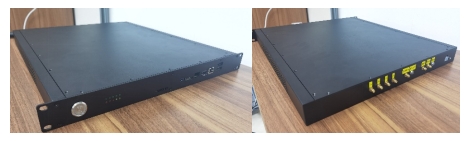
Fig. 14. the low-latency DBPM processor prototype.
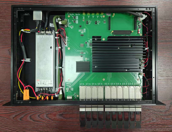
Fig. 15. the low-latency FOFB controller prototype.
Mechanical Support
The storage ring mechanical support system provides a common mounting platform for equipment such as magnets, vacuum components, and beam diagnostics, while also enabling precise positional adjustments. Various types of magnets and other devices are installed in the storage ring tunnel via magnet girders. Utilizing a two-stage adjustment mechanism, each magnet is accurately positioned to meet the requirements specified by the physical design. The magnet girders are essential foundational components for the integrated installation of storage ring magnets.
Fig. 16 shows the structure of a magnet girder. All components of the magnet girders were independently designed and domestically manufactured. The adjustment resolution and vibration performance are comparable to international counterparts, fully meeting the overall technical requirements of the HALF storage ring.
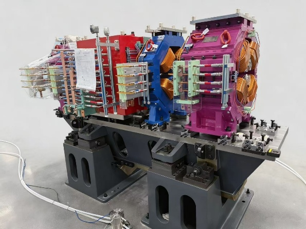
Fig. 16. High-Precision and High-Stability Magnet Girders.
Insertion Devices
The insertion devices system aims to offer the diffraction-limited photon beams to various experiment stations. Eleven undulators and two wigglers will be commissioned at the end of 2028, with the photon energy covering from 5 eV to 30 keV. The unique photon beams are characterized by flexible polarization tunability and good spatial coherence especially from VUV to soft X-ray wavelength region.
The HALF insertion devices include six elliptically polarized undulators, two in-vacuum undulators, two planar undulators, one helical undulator and two damping wigglers. Two planar undulators are self-developed with the photon energy covering from 180 eV to 2.5 keV. Up to now, one helical undulator as shown in Fig. 17 and one elliptically polarized undulator as shown in Fig. 18 have been manufactured and tested well. Other undulators are still in progress.
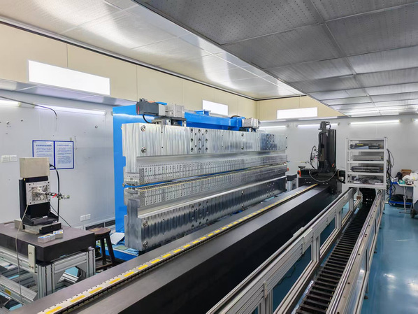
Fig. 17. Helical undulator (HU115).
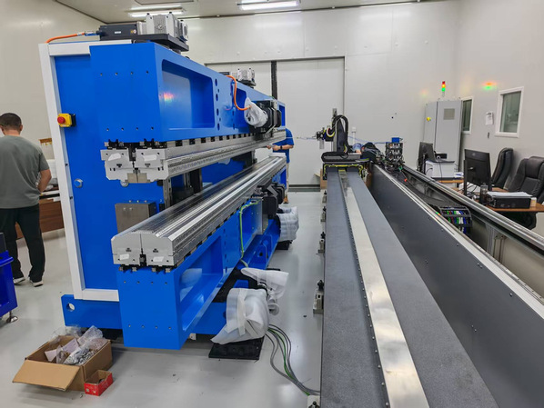
Fig. 18. Elliptically polarized undulator (EPU42).